Replacement of rolling cage guides – measurement support in metallurgical conditions
Metal smelters are working environments where equipment is exposed to extreme conditions: high temperatures, dust and intensive operation. These factors not only affect the durability of components, but also the geometry of machines and their guiding elements.
One of the key components of a rolling line is rolling cages. They are responsible for the rolling process, i.e. the plastic deformation of metal between rotating rollers to give it the right shape and dimensions. The precise alignment of the cage guides has a direct impact on the quality of the product and the stability of the process.
We recently participated in a project to replace rolling cage guides at one of the steel plants, providing comprehensive measurement support.
Scope of survey work
Our activities included full geometry control during the upgrade process, including:
- input measurement of depleted guides,
- Determining their actual position in space,
- Support for positioning of new guides,
- Ongoing monitoring of the setting during installation,
- final measurement to confirm the correctness of the work.
The goal was to maintain the correct geometric relationships and ensure the correct position of the new elements relative to the entire rolling cage structure.
Measuring the position of old guides
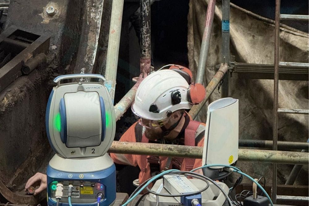
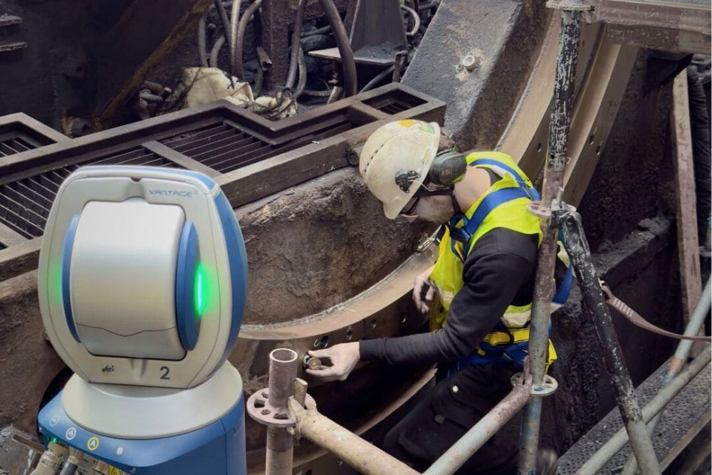
The first step was the input measurement of old, worn guides. For this, we used the FARO Vantage S laser tracker, which allows precise position measurement in 3D space.
This provided us with data on:
- position deviations,
- Parallelism and straightness,
- Geometric relations with respect to the axis of the rolling cage.
The information collected provided a reference point for further assembly work and made it possible to assess the degree of wear on the components.
Positioning of new guides
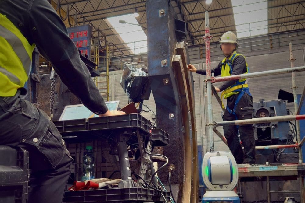
After the old guides were cut out, the assembly of the new components proceeded. At this stage, it was crucial to position them precisely – both in terms of position and to maintain the required geometric relationships.
Our task was:
- Determining the target position of the guides,
- Dimensional and spacing control,
- Ongoing monitoring of the setting during the welding and clamping process.
Due to the long-term nature of the assembly, the position of the components was constantly monitored. If necessary, we made adjustments to prevent deviations due to stress or temperature changes.
This approach avoids a situation in which only the final measurement reveals nonconformities that require rework.
 Final measurement and geometry check
After the installation was completed, we took a final confirmation measurement:
- The correctness of the alignment of the guides,
- maintaining the required dimensions,
- Compliance of the items with the design assumptions.
In order to better visualize the results, we additionally used scans taken with the FARO Focus point cloud scanner. The acquired point cloud enabled detailed analysis of the geometry and clear presentation of the results in technical documentation.
Technical report on the upgrade
The culmination of the implementation was the delivery of a report to the client containing:
- summary of measured values,
- deviation analysis,
- 3D visualizations and control sections,
- Confirmation of the correctness of the upgrade.
The documentation is a formal confirmation of the quality of the work performed and a safeguard for further operation and possible technical audits.
If you are facing similar tasks in your company, call us for a ready-made solution. Please visit our contact page .